Updated: 2019 March
2020 Feb 14
2025 July
|
Techniques used for the study of time dependant astronomical events, particularly Lunar and Asteroid occultations of stars. Including some observing equipment. |
|
a)
Preamble
b) Orbit Uncertainties
1. Geographical
Coordinates
2. Which Time Signal ?
3. How bright is the star?
4. Stopwatch or chronometer
5. Audio Observation and tape analysis
5a MSF time receiver
6. Reaction Time
7. Video
8. Video / VHS Tape
9. Video accuracy
10. Fast Frame Rate
11. Integration time
11aCombined Visual / Video observation
12. Video Time Overlay
13. Digital Video
14. Video Grabber VHS to PC
15. DV tape to PC
16. Video Grabber and calibrated clock
17. Drift Scan and Manual drift scan with DSLR
18. Primary Time signals sources
19. Secondary Time sources.
20. Reporting
21. Software
integration of TANGRA 3, OCCULT 4 and OccultWatcher
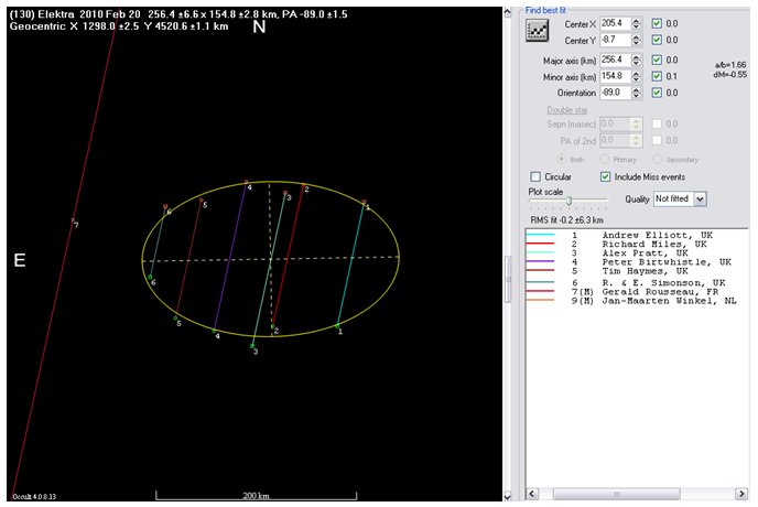
Preamble
Successfully
recording the time (UT) of disappearance (D) and reappearance (R) of a
star provides information on the position and size of the asteroid. With
more spread out observers the asteroid shape
can be deduced. Detection of D and R with a telescope can be made
by eye (visual) or with electronics (Video / CCD). Visual observation
needs a 20cm or larger aperture (25-30cm) in order to see and monitor
stars of 10th to 11th magnitude clearly. Some times stars may
be 7th to 9th magnitude, but these are quire rare events.
Electronic
detector/recorder combinations will produce a permanent record of the
event for re-play and further analysis and smaller instrument can be used
(8 to 15cm). Reliable timing is important, so a UT time signal is recorded
with the observation. The techniques described here have been used successfully
by many observers. Asteroid occultation predictions can be obtained from
internet resources (EAON)
and globally. DeskTop
software by Dave Herald (OCCULT
4) is used to generate predictions, or alternatively use Occult
Watcher software
The current version of OCCULT 4 is 4.9.5.2
(as of 2020 Feb) 4.2025.6.22 (as of 2026
June)
Occult Watcher
3.7 is the recommended Windows XP software. The supported version for
W7 upwards is 4.6. (The
soft works in W10/11)
TANGRA 3.6 is used for the analysis of video
AOTA is a tool from Dave Herald for detailed video frame analysis generated
by Tangra. It is available in Occult4 and can be launched from Tangra.
<Top>
Orbit
Uncertainties
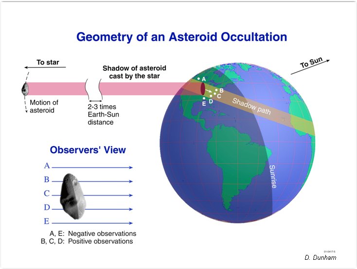
There are small errors in the orbit of an asteroid
and the position of the star. This results in a likely shift in the track
away from the observer, who then sees a shorter occultation or "miss".
Or indeed the shift may work to an observer's advantage if he/she is not
in the track but the shift is towards the observer. See this graphic
by David Dunham. A miss (or no occultation) is a negative
observation and should be reported.
Uncertainty and errors arise from:
- Star positions (10 to 30 mas) NOTE: The Gaia Mission will reduce star position errors to about 1 mas for 1 billion objects.
- Orbital positions (10 to 100 mas)
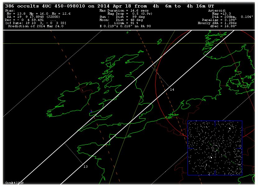
Compared to a main belt asteroid diameter of 30-50mas, the prediction uncertainty can be 2 or 3x the asteroid diameter. The errors are displayed on the predictions. Observations in 2018 and 2019 indicate shifts in some lower numbered asteroids of 1/2 to 1 diameter.
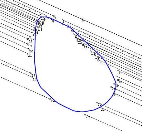
Example: Occult4 prediction for (386) a 208km diameter asteroid (solid lines). Dotted lines enclose the most probable area for an occultation.
Future data releases from Gaia DR2 will include asteroid astrometry, and resulting improvements in predictions.
<Top>
1.
Observer's Geographical Coordinates
GPS is the preferred longitude and latitude datum for an observer,
referred to as WGS84. This has superceded the Ordnance Survey datum OSGB36.
The two coordinate systems refer to the same spot on Earth, but the co-ordinate
origins are different. Read the Wiki.
You can read them off Google Earth using the cursor to an accuracy of
about 5 meters. I have checked my carefully surveyed observatory's OSGB36
coordinates and the mathematical conversion to WGS84 matched the Google
Earth location exactly (to +/- 0.1"). After May 2000 the deliberate
inaccuracy introduced into GPS caused by "Selective Availability"
was switched off, so that GPS now provides the required accuracy in longitude
and latitude.
Height above mean sea level is also required when reporting events. I give heights to the nearest 10 m above MSL. Look up http://www.streetmap.co.uk 1:50000 for height information, or use GPS. Google Earth gives heights also (not to be confused by "eye-height"). Turn on the Terrain layer.
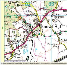 Map (left): The contours and spot heights are still usable
<Top>
2.
Which time signal?
Timing accuracy for occultations is crucial. There are some time signals
that should be avoided such as from TV channels and un-calibrated computer
clocks. Some phone networks (e.g. Virgin - thank you to Andrew Bate for
this information) can produce a time signal, but accuracy might be unreliable.
Primary time sources are listed in section-18. These are generated from
atomic clocks and transmitted to telephone land-line (in the UK), Radio
signal, and GPS
equipment. In practice one of these time signal should be used to synchronise
another clock which could be electronic or electromechanical with a constant
rate, and this is used at the telescope. A recent development is the use
of GPS as the time source and this is rapidly becoming the preferred method
for video occultations.
GPS video time inserters are now preferred for video. The time text overlay
is inserted each video frame to 1ms. See section 12
Visual observers using stopwatches or synchronising clocks to UT,should consider using use a PC application written and maintained by astronomer Hristo Pavlov "Beeper Sync 3.3" http://www.hristopavlov.net/BeeperSync/. This is a well characterised method and provides reliable 1 sec ticks using a wired internet connection. (Wireless might introduce additional time delays - this should be assessed by the user).
Update: Visual observation is fun, but not suitable for critical analysis unless supported by video detections.
<Top>
3.
How bright is the star?
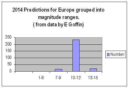
Stars occulted by an asteroids are quite often faint (typically 10-12th
magnitude). The prediction histogram for star magnitude indicates 90%
of occulted stars are 10th-12th magnitude (in 2014). Only a relatively
small number are brighter and observable by eye with a small telescope.
Hence the need for video.
Occasionally some are brighter; and there are two events (D and R) to be recorded in succession. The interval (or chord length) can range from 1 to 30 seconds. If the asteroid and star are of similar brightness the magnitude drop (dM) is small. Under these circumstances (dM < 0.7) an observer might not see the event, or his/her reaction time may be longer (up to 1 second). Short occultations (less than 1 second duration) are subject to larger timing errors and uncertainty because the duration is close to the observers reaction time. ( Reaction time can be avoided by using video Section-7, or Drift Scan Section-17). The magnitude drop is part of the prediction and is an important consideration that will influence the method of observation.
<Top>
4.
Stopwatch and Chronometer
Most visual observers will be familiar with the “stop watch and
telephone pips” method of timing. Start the watch (or multi-function
chronometer) at the instant of occultation and stop the watch at a known
second provided by a telephone or radio time signal. (Note: Use BT land-line
in the UK). Lunar Occultations are often timed by this method.
|
The observation time is then calculated: |
A lap mode setting can record an interval while the watch still runs. PE can be estimated. See Section 6
<Top>
5.
Audio observations and tape analysis
One solution to recording events in quick succession is to use
an audio tape recorder with a UT clock tick
or radio time signal superimposed. Remember
to announce a minute marker at the start and end of the recording. Analysis
involves counting all the seconds. This takes time, and the process needs
to be double checked, but the record is permanent and can be re-evaluated.
Those who have Lunar grazing occultation experience will already be familiar
with this method of recording. Some observers have digitised the audio
which makes analysis easier.
The iphone and other smart phones can record audio, and the files emailed
and analysed with free software such as Audacity.
The author has used a camcorder video ( Sony TRV 22E) as an audio recorder while using the internal clock as a time overlay (synchronised to UT).
(Update: May still be useful for Lunar Graze occultations, but audio on top of Video is good !
<Top>
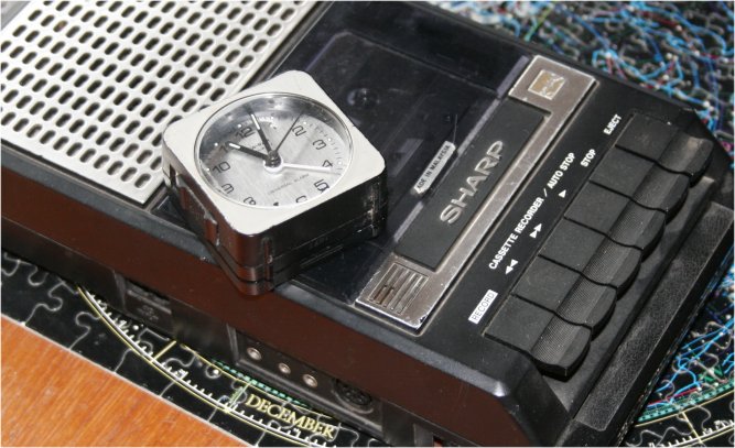
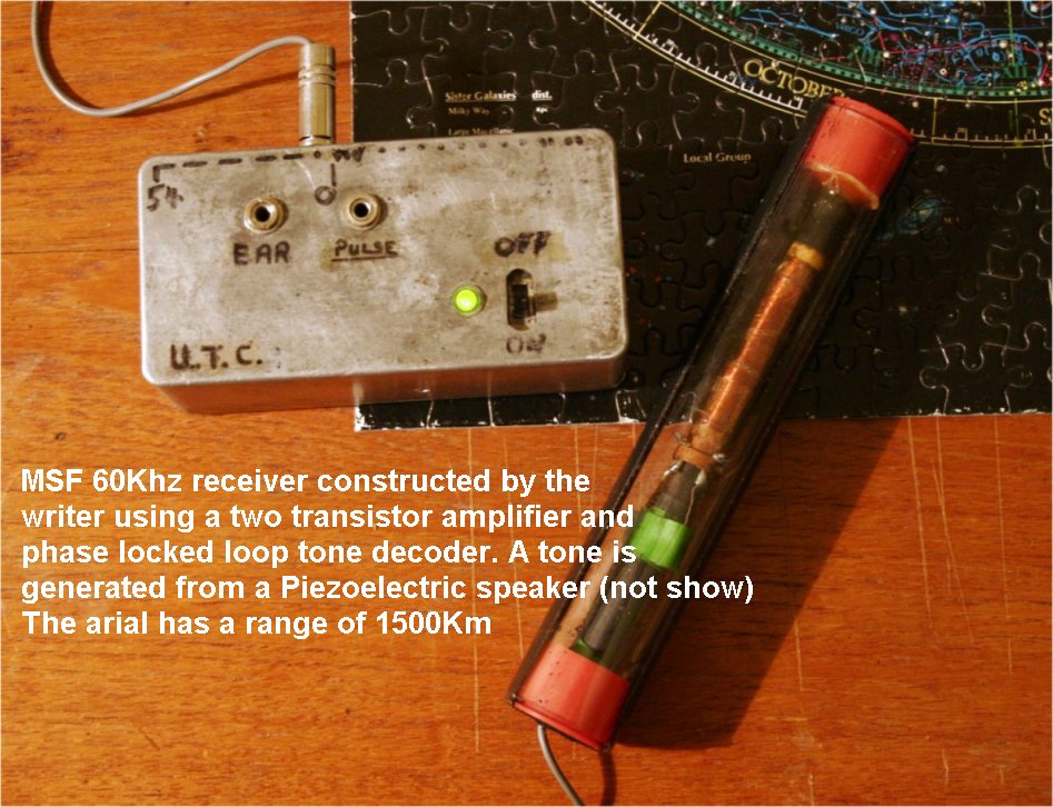
MSF
Receiver
An MSF 60 KHz
receiver on a 4x1 inch Veroboard was build by the writer in 1974/5 based
on articles in Wireless World. This was the result.
The aerial was tuned
with a micro volt meter, but can be made from a standard long-wave coil
- see here
Output is pips at 1 sec intervals. Commercial radio (MSF/DCF) clocks are
now quite cheap, so building a dedicated receiver is not economical.
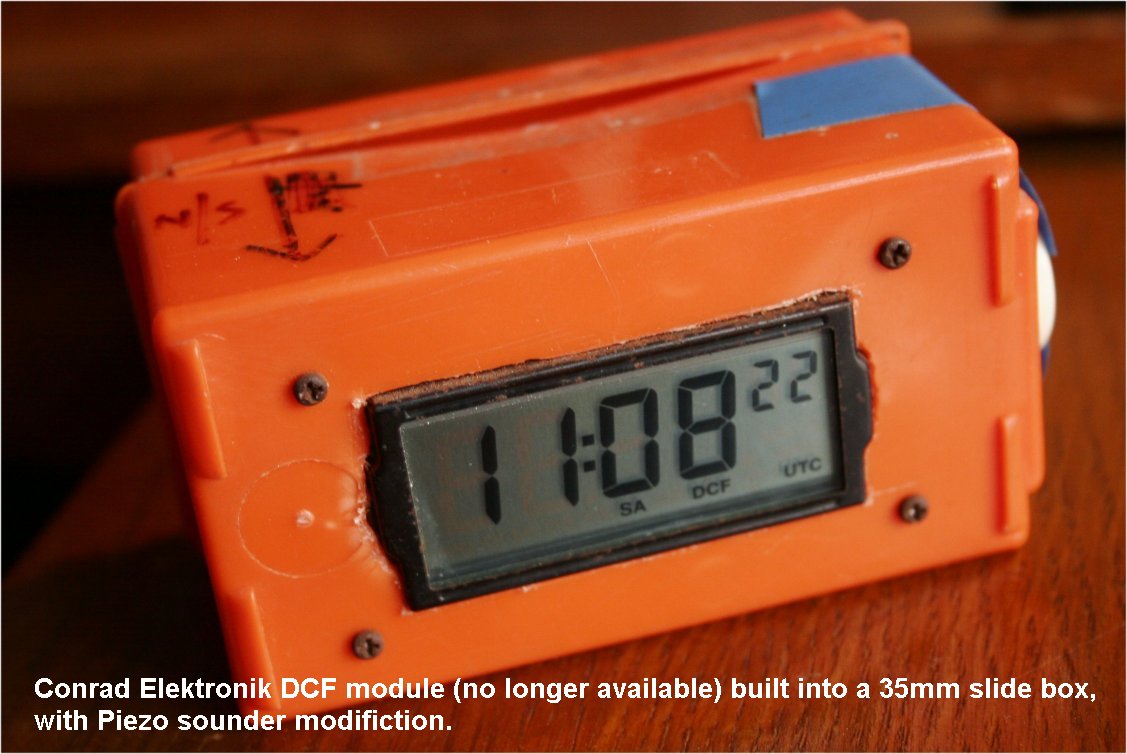
However the writer (in 2018) made a DCF beeber from a radio clock printed
circuit - it was modified by addition of pizo sounder and produces pips
but no analogue UT time. Cost of the box and bits was about £20,
and the circuit board about £7
Note added 2020 Feb: Highly integrated circuit modules for DCF77 front-end receivers, may not give accurate 1 pulse per second (1PPS) output. I used one of these as a simple LED seconds pulse for testing cameras and other timing equipment, however there are errors introduced that make the IPPS unsuitable for estimating errors of less than 20ms. The home made MSF receiver does not suffer in the same way, and is good to 1 ms
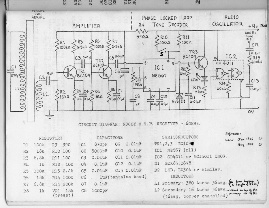
Diagram of an MSF received (above) drawn by John Toone and reproduced
from The Salford Astronomer (1977)
(Update 2026: Secondary time pulses like this can be used to check some GPS equipment. This second level of check is very useful)
<Top>
6.
Reaction time (reaction delay or Personal Equation)
An observer's Personal Equation (PE) is subtracted from the recorded observation
time. PE is the largest uncertainty in timing by visual means and depends
on physiological factors. In the end PE may only be an estimate for a
difficult conditions e.g. 0.5 +/- 0.2 sec. For clear events (bright star,
good conditions) reaction time can be in the range 0.2 to 0.3 sec depending
on the observer. There are methods of estimating reaction time. The dropping
ruler method, software simulation or on-line
app's. The author has used a stopwatch to time an asteroid and lunar occultation
from a TV monitor, and compared it to the same event on Video. The reaction
time is consistent for bright stars by direct vision. The estimated times
of fainter events required greater PE correction (0.5-1 second). Estimated
errors should be realistically reported.
( Update 2026: This technique is of historical interest. Modern video and GPS time has no Reaction time to consider)
<Top>
7.
Video.
An integrating video camera has become the detector of choice for asteroid
occultations. Watec120N,
120N+ and Mintron 12V6HC [and now the WAT-910HX],
are used by amateurs with excellent results. The camera has other applications
such as meteor detection, or as a finder, or as an auto guider. Video
produces a permanent unbiased record without reaction time uncertainties.
The exposure can also be adjusted to suit conditions (magnitude drop,
instrument aperture, seeing), so it is a versatile piece of equipment.
There is a readout time ( half the frame or integration time) to be subtracted
from video times. See Section-9
(Update 2026: Only the WAT910 HX and Night Eagle Astro are in current usage )
Cameras in
use - some are now unavailable (*).
Mintron 12V1C-EX
Mintron 12V6HC-EX
PC165DNR (*)
SCB-2000N
WAT-120N (*)
WAT-120N+ (*)
WAT-902H
WAT-902H2 Ultimate
WAT-910BD
WAT-910HX
Malincam
Runcam Night Eagle Astro
The Watec 902 H camera is used extensively (and costs less) but does not have an integration function. (It runs at 50 or 60 fps).. The Current WATEC integrating camera is the 910HX/RC. It is still the most sensitive detector (as of 2020 Feb), but supplies of new cameras are not being replenished.
8. VHS video
tape
VHS is a simple option to record from the video camera. It will also record
a time overlay by inserting a time and date generator into the video signal.
The result is a permanent record of the event. VHS video can be digitised
for analysis on a PC, or played back frame by frame.
(Update 2025: Of historical interest)
<Top>
9.
Video Accuracy and detector "dead" time
Video introduces improved accuracy, with 0.04s time resolution. (0.02s
for the WAT 910HX at field level). Compare this to a visual observer who
at best may achieve +/- 0.1s accuracy. You will find integrating video
observations reported with errors larger than 0.2 sec, this is due
to the integration time, and isn't a reaction time. Video doesn't
suffer from "detector dead time". This is the time when a CCD
camera is not exposing, but is saving the previous image. The time taken
to download a 16 bit CCD frame is 0.6 to 1 sec (Depends on the computer
specification, binning and subframe settings). The download time can be
estimated, but a short occultation might not be detected if it happens
while the CCD is waiting to record the next image. With video there is
no delay other that a time correction which is a constant for a particular
camera. Details can be found on G Dangl web site.
Gerhard Dangl's video timing analysis http://www.dangl.at/ausruest/vid_tim/vid_tim1.htm
Gerhard Dangl's M67 IMAGE comparison http://www.dangl.at/ausruest/cam_comp/cam_comp.htm
16bit FITS images can be recorded with minimal dead time if 25%sub frames and 2x2 binning is tried. Consider using this arrangement when seeking the best S/N on a faint objects, and when the event could be of long duration.
(Update 2025: CMOS cameras have no appreciable delay or dead-time between frames. Frames can be lost though - check the data rate)
<Top>
10.Frame
rates
Low light monochrome video has the ability to detect short events, non
instantaneous events or other unusual phenomena like double stars. Some
CCD camera used in sequential imaging can reduce the dead-time by setting
a smaller region of interest.( ROI ). Also the ATIC Titan is reputed to
operate at 10fps or faster. A USB2 web cam (e.g. Image Source) can also
operate at a range of different exposures (and frames rates). This is
untested, and accurate time stamping is a difficulty. USB 3 cameras work
at fast frame rates in SER mode.
Some recent digital web cams can operate at 60 fps (or more). This has not yet been fully exploited for occultations. Current versions of FireCapture and Sharpcap with USB3 cameras are producing good results with NTP when calibrated.
From 2019 the
QHY174m-GPS provides a CMOS output with UT frame stamps in USB3 connection
operated from SharpCap 4.1software. Frames rates are possibly from 1fps
up to 100 fps . This camera is also a deep sky camera. Asteroid photometry
is a collaboration project. 30sec exposures are typical
Reports are coming through of planetary cameras used for occultation work
at 5 fps (200ms exposure).
<Top>
11.
Integration time using an integrating video camera.
The aim of video observation should be to use the smallest cadence time
the telescope and weather conditions will allow. This will require some
experimentation beforehand. For example a 20cm instrument in good conditions
can record 12th magnitude stars in 0.16 sec, and a 30cm to 13th magnitude.
So a 20cm can record most of the predicted events from EAON and IOTA using
an integrating video camera, and fainter objects by extending the integration
time. The author finds that a short integration time of 2 frames ( 2/25
sec) helps to smooth out seeing ripple in bad seeing conditions. 10cm
and 15cm instruments can be used with longer video integration times.
A maximum of 0.64 second exposure should be considered as giving the best
compromise between detecting the event (s/n), and time accuracy in smaller
apertures. (5cm - 15cm)
Note: MINTRON cameras should be used at frame integrations that are multiples: e.g. 2,4,8,16. etc and not intermediate rates if these are provided.
ALSO the MINTRON and WAT-910HX count in fields and not frames. 2 fields = 1 frame !
<Top>
11b Combined Video / Visual observing
Displayed on a monitor, video will produce a bright clear images that could be timed with a stopwatch, but it is preferably to record the event either on tape (VHS, Digital Camcorder / Video 8 ) at the same time. When operating at 25fps, the PE has to be taken into account. If using an integrating camera, the combined PE and camera delay are summed.
A video monitor displays video almost instantaneously, however this cannot be done with a laptop screen.
12.
Video Time Overlays
There are two choices, either obtain a
time and date generator (TDG) with manually sync to UT, or a GPS time
inserter.
A) GPS
The GPS system produces a time stamp on every video
frame to a precision of 0.001 seconds. It is the convenience of analysis
of a permanent record that makes this method so attractive. Here are some
commercial GPS units:
GPSBOXSPRITE3
by Blackbox. Here is a screen shot
of the Sprite in use, and You
tube demo of the Sprite.
AME-TIM10 by Alexander
Meier Electronik. Here is a You
tube demo of the TIM10.
Kiwi-OSD system is no longer available commercially, but is used by many.
IOTA-VTI3 is a new addition to video time insertion via GPS, and is designed to give best results for occultations. It can be purchased from Video Timers and it will be maintained for the future.
<Top>
B)
TDG
A Time
and Date Generators (TDG)
is reliable but it doesn't’t produce an exact time on each video
frame. The TDG clock is manually synchronised to UT ( e.g. from telephone
land line, radio or NTP) and to obtain the time of each frame, the user
advances the video one frame at a time until the frame in which the disappearance
is reached. The fraction of a second can then found. Single frame advance
is available on most better video players. This is made easier if the
video is digitised and analysed by software e.g. Limovie and TANGRA. Both
these programs are free down loads. TANGRA
3.1 is the easier to use and some automated analysis can now performed
(Update: Manually time-synced equipment needs a second time reference from a reliable source)
<Top>
13. Digital Video
Recording.
The author uses a DV camcorder with analogue to digital conversion (AV/in)
built in. There are several makes available second hand (Sony and Canon
i-series). The video output is plugged into the camcorder AV/in for display
and recording. Newer equipment might also do this (unknown). DV cameras
operate on their own batteries and are highly portable - Beware that tape
heads need to be cleaned. A dirty tape head could spoil your recording.
Remember to clean it !
(
Update: Only possible with care, but is a good recording format that avoids
computers at the observation. Working cam-corders are hard to find !)
Digital Video (DV) cameras capable of A to D conversion (known or reported
to the author by David Dunham and others) are:
Sony: TRV22E,
TRV33E, TRV480E
Canon MV600i (an others in this series), MVX25i
Canon ZR camcorder models 60, 65, 80, and 90 (and other "i"
models not beyond 300i)
Canon MX2, Canon XL2, Sony VX2000, Sony VX2100, Sony PD 150 and Sony PD170 are camcorders with better quality than consumer level equipment. I'm a permanent user of VX 2100 and PD170 - writes Pawel Maksym (pl)
A comprehensive
list is here
http://www.4kam.com/camcorders_with_av-in_av_input.htm sent to me
by Jan Manek (update 2011Sep13)
<Top>
14.
Video Grabber VHS to digital
Recording directly to VHS tape and viewing on a monitor or TV is straightforward
to set up. This may be sufficient for your needs if the VHS player has
single frame advance for analysis. Digitization of the tape can be beneficial
for post analysis with Limovie. You might already have a PC with a suitable
video card, but at the end of the day, you are going to analyse or archive
the video data in a PC readable format (e.g. AVI, DivX). The simplest
method is to invest in a USB Video Grabber (Analogue-to-Digital). They
are supplied with software for video editing which you might not need,
but it would be advisable to install as there may be a feature you need
later. For W7 to W10 the writer uses the Pinnacle Dazzle (HD)
There are software tools available such as the freely downloadable VirtualDub. This will detect the Video Camera (or VHS tape AV-out) and digitise the signal. I select a file name and duration for the recording, set the frame rate to 25.000 fps and record – test your system before the event and make any adjustments. Check you have auto file name increment enabled, so that previous files are not deleted.
One point to note is that the bottom of the frame might not be digitised by the video grabber (The Author’s did not). This results in the TIME overlay at the bottom of the screen being lost. The answer is to put the time stamp at the top of the frame or change to the digital resolution in VD
(Update 2025: VHS tape is of historical interest maybe - such as archiving old observatons in digital format )
OccuRec and IOTA video capture are two programs (download is free) that are designed for occultaton video capture. Both have a schedule facility to start recording at a specific time.
<Top>
15.
DV tape to PC or Laptop
Currently the author transfers DV tape direct from his Camcorder by firewire
to the XP PC which was bought with firewire installed. W7 was the last
operating system to provide fire wire. There are no drivers for W10. Novatech
computers (UK) will make a custom build where possible. But from 2019
and W10, the recommendation to use video capture to the hard drive or
SSD.
16.
Video Grabber and Calibrated PC clock
Some observers use a calibrated PC clock to time stamp the AVI obtained
from VirtulDub. The Author uses free software Dimension
4 which applies a correction to the PC clock by connection to the
internet. The displayed PC clock (Windows Date and Time Properties) is
not more than 0.05 sec different to UT immediately after synchronisation,
and over 24hrs the drift is +/- 0.5 s. Some observers prefer to use GPS
than rely on a PC clock. If frames are dropped on a PC, the timing becomes
less accurate.
(Update 2025: Any PC clock is dubious at best, unless calibrated by GPS with a continuous log file )
<Top>
17.
Drift Scan and Manual Drift Scan with DSLR
The drift scan method
is described here by John
Broughton. The occulted star is allowed to drift across the detector
controlled by software. A stellar occultation appears as a break in the
stars trail.
(
Update 2025: Still a usable method, but requires care and advance planning
)
Manual
Drift Scan with DSLR
Focus a DSLR and position the star near the East
side of the frame so that it will drift across the longest side. Start
the audio tape recorder with time signal.
Then about 1 min before the event, simultaneously switch off the telescope
drive and open the camera shutter. The sound of a “switch throw”
or “shutter opening” should be audible and recordable. This
marks the start of the exposure. Now close the shutter after a predetermined
time (sound is recorded again). The length of exposure should made less
than the transit time across the field, with the predicted time of occultation
occurring near the center of drift.
Example:
Drift scan at declination delta for Canon 60D and 300mm lens ( updated
2020 Feb 18)
Focal length (FL) = 300mm
CCD resolution (Canon 60D) = 3456 x 5184 Hpx Lpx in pixels
Canon APS-C dimension = 15.0 x 22.5 Hmm Lmm
Declination of star = +39 (say)
Cos delta = 0.777
DSLR Field of view (long side) = Lmm x 57.3 / FL = 4.3 degrees
DSLR Field of view drift time (1deg = 4min) = Lmm x 57.3 x 4 / FL = 17.2
min
DSLR drift time at declination delta (degrees) = Lmm x 57.3 x 4 / (FL
x Cos delta) = 22.1 min
Drift in pix/sec at delta = Lpx / (22.1 x 60) = 5184/1326 = 3.9 pix/sec
OR 1 pix drift = 0.26s
Formula: 1pix drift = 309420 / ( Lpx x FL x COS delta) seconds, for a
Canon 60D
Experiment with the ISO settings so that the frame is not unduly overexposed, as this might effect the measurement of the star trails. A focal length of at least 480mm is suggested (e.g 80mm F/6) to provide reasonable time resolution by the drift scan method.
A 300mm lens (example above) may be used on longer duration events of say more than 5 seconds. A 300mm F/5.6 will have a limiting magnitude of about +10 in sidereal drift mode.
(Update: Calculation may need checking)
<Top>
18.
Primary Time Sources
1) Telephone (BT 123)
2) Audio radio reception (Many stations world wide, three are selected)
- (Update : WWV in the US is perhaps one of the
last short-wave stations in use.)
a. MSF (UK) 60 KHz long wave
b. DCF77 (Germany) 77.5 KHz long wave
c. WWV (Fort Collins US) 5000, 10000, 15000 KHz Short wave (Try 5000 in
the UK)
3) Global Positional
System (GPS) - this is the US system, and requires a +18 second correction
obtained from a downloaded almanac (That can take 10mins).
a. GPS receiver that contains a one pulse per second clock (1pps) and
associated electronics to generate and display precise UT
b.
GPS disciplined NTP via RasPi - home made.
c .GPS disciplined USB2 (TimeBox)
Update 2025 Oct: The Galileo system is a UTC time pulse that doesnt need a correction like GPS. Sometimes its possible to select satelites with software.
4) An observatory
clock
a. You have access to a professional system perhaps.
b. A clock that displays UT based on radio reception (commercial or home
made).
<Top>
19.
Secondary Time Sources (Clocks synchronised to UT with established time
difference)
1) Atomic wrist watch – time automatically synchronised by a radio
time signal. There might be a small internal delay in the LCD display,
but an analogue display should be fine.
2) PC internal
clock set by an internet time or GPS service.
a. Clock controlled and
updated by a well established application. (e.g Thinking Man Software
Dimension 4 or Meinberg)
b. Beeper
Sync application that produces pips via internet (no
longer used ?)
3) Other clocks
with established errors ( i.e. “running fast / slow by:” )
manually synchronised to a Primary time signal
[ NONE RECOMMENDED FOR ACCURATE OBSERVATION
]
a. Video Time and Date Generator (TDG)
b. Quartz crystal controlled analogue clocks (electromechanical)
c. Electronic metronome (pips).
d. Camcorder with an internal time display HHMM ss.
e. Stopwatch or multi-function chronometer started or stopped on a UT
second.
f. Digital wrist watch
<Top>
20.
Reporting.
a) Asteroids (UK / Europe)
First report ? Then send to
the BAA ARPS occultation coordinator for checking ! Thanks Tim
Haymes
Fill in the EAON report form
and send it electronically to Tim haymes
This form can be pre-filled from OccultWatcher to avoid mistakes.
SODIS
is the current database for
European observations (as of 2023). Contact SODIS admin or Tim Haymes
Register with PLANOCCULT http://vps.vvs.be/mailman/listinfo/planoccult
b) Using OccultWatcher software and sending to the European Collector
Author: Tim
Haymes
Assistant Director (Occultations)
Asteroids and Remote Planets Section
British Astronomical Association.